October 02, 2003
D-Link DWL-G650 AirPlus Xtreme Wireless G Card
Wireless G cards. Buy.com had a deal I couldn't resist, especially since I needed a new wifi card. The DWL-G650 was going for $35 after rebate (I quickly sent in the rebate, of course). Sadly, it was sort of an impulse buy, considering that I didn't research whether or not the card had an connector for an external connector -- you never know when you need more POWER! Well, the geek in me made me quite impatient after getting the card, I just had to open it up to find out whether or not I could add a connector. Lo and behold, after opening the card, there was already a connector attached to the PCB! Actually, this wasn't that surprising, since others on the net reported the the D-Link DWL-650+ (802.11b) card also had a built-in connector and all that was required of you to use this connector was to drill an access hole and move a capacitor. Obviously, I decided, then, to drill a hole to access the connector on the DWL-G650 (as shown by my pictures). The card is actually not too difficult to open, and the plus of this card is that there appeared no glue was used to put the external case together, so re-assembly of the card was a snap, literally.
To start disassembling your card, first you must take apart the plastic panel on the back of the card, as shown here:
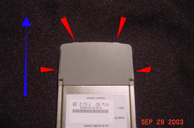
There are four tabs (shown by the four red arrowheads) that attach the backpanel to the plastic housing. You just need to use either your fingernails or a small screwdriver (or both) to pop the tabs up and out. Then to remove the backpanel completely away, just push or pull the backpanel in the direction of the blue arrow. The next step is to take the card apart in half by removing the top cover, which consists of both the remaining plastic portion and the metal housing.
The lines in red show the outermost groove lining the sides of the card. This groove corresponds to the end of the metal portion where the back wraps around to the front. You will need to move aside this wraparound portion. Again, using your fingernail (preferred) or a small screwdriver, pry into the groove and gently pull aside the wraparound portion (without bending the metal too much) out and under the top metal cover along the one entire side of the card. Then work on the other side. Work slowly and carefully. You should come to a point where you can take the two pieces of the card's housing apart as so:
.JPG)
One part is just the top portion of the card, a shell that is made of two pieces, one plastic, the other metal. The bottom portion of the card has the connector and board attached to the metal shell. Once you have the top portion removed, you should see the top of the PCB. The part of interest should look like this:
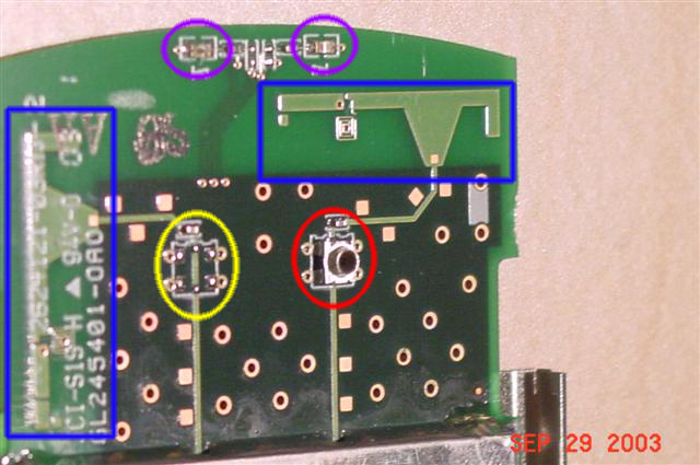
The connector circled in red is the connector of interest. I believe it's either a MMCX connector or a reverse polarity (RP)-MMCX connector after comparing pictures at Amphenol Connex. However, I am not completely certain which one. If someone knows for sure, please let me know. There are a few points of interest, looking at this board. What I circled in yellow looks like another spot where you could solder in another surface mount connector (to make it a total of 2! external connectors). Boxed in blue, I'm highlighting what I believe to be the antennas onboard. If you follow the circuits for either antenna, you can see that for both, the circuits are closed with capacitors that are also encircled within the yellow and red regions. This leads me to believe that the external connector probably works without a need to modify the card any further. I am probably wrong about this, but I will never know for sure until I test it (I'll need to buy a N to MMCX pigtail or N to RP-MMCX; anyone care to "donate" one to me, so that I could test it out ;). Now, just eye-balling the relative position of the connector in relation to the LEDs circled in purple, I chose a spot in the plastic to drill a hole and dug through to get:
.JPG)
As you can see, I removed the sticker to get a clean hole drilled. I also sanded the sides of the hole with a sanding bit on my dremel, just to make it less jagged. Now, all I need is that pigtail, and I'm ready to go. BTW, reassembly of the card is just the same as disassembly, but in reverse.
The D-link drivers and software for this card already has a rudimentary stumbler type of application whereby I can search for APs AND check the signal strength and link strength. All in all, this 802.11g card is quite the bang for the buck. I just can't wait until the PrismGT chipset on this card is supported on linux. Good luck to all of you attempting to get access to your connector, as always, I take no responsibility in the damage you do to your card, this information is provided with no warrantees whatsoever.
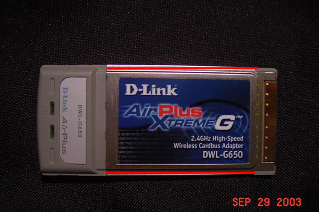
Posted by johnvu at October 2, 2003 01:23 AMYour first pic on page with DWL-G650 shows H/W:B2 F/W:2.20
If I look in H/W:B2 Driver file update it shows Atheros chip part numbers rather than the PrismGT you mention on your page.
"I just can't wait until the PrismGT chipset on this card is supported on linux."
Posted by: silent type on October 9, 2003 12:17 AMST, thanks, that's good to know. Would you happen to know if the Atheros chip is supported in Linux yet?
Posted by: John on October 9, 2003 11:56 AMIt is, try http://sourceforge.net/projects/madwifi/ works like a charm with my WAG511. Also interesting sites are http://www.mattfoster.clara.co.uk/madwifi-faq.htm and http://madwifiwiki.thewebhost.de/wiki/
My real question would be, if you succeeded in connecting an external antenna with your connector, as I opened my card and found a similar connector on it...
Posted by: Alex on October 12, 2003 09:17 AMI just tried to use a MMCX connector to connect the antenna to the card and it didn't work. I'm going to by a (RP)-MMCX connector tonight and see what happens with that. Thanks for the info...
I'll give you an update how well it worked in a few days.
I think it's some kind of hirose u.fl connector.
They seem to be pretty much standard on miniPCI cards, so why not Cardbus ones too? There's a data sheet here: http://www.farnell.com/datasheets/33433.pdf
I'm not exactly what part it is though.
It is definitely the connector that Matt posted. So it looks as though we will need the U.FL-LP-040
connector(pigtail). I just bought the DWL-G650 and I am dying to put an external antenna on it. I am trying to make my own connection to the card.
This card is available for $33.74 after rebate, free shipping. http://www.amazon.com/exec/obidos/tg/detail/-/B00007LTB6/002-5654379-5989607
Posted by: John on October 21, 2003 03:59 PMAnd where can I find a connector to use with the card?!?
Posted by: xyber_mouse on October 22, 2003 05:21 PMCheck out http://www.fab-corp.com/index.htm
and do a CTRL+F search for "U.FL"
It's 29.99 and I bet it's just the connector you are looking for. Looks like you might need to drill some more room for the right angle, or maybe it would fit under the panel with no holes in the top. Maybe just a hole on the side for the cable to come out of.
Let us know if it works!
Posted by: Brenden on October 23, 2003 04:21 PMAnd just for the record: did anyone tried to connect an external antenna?!?
Did it work? Good results?
I just finished my external antenna and I am going to try it tomorrow. I could only get two good connect out of a dozen. So hopefully I can get 100% connex now.
Posted by: Josh on October 25, 2003 09:45 PMYou need to remove the zero ohm resistor just past the connector very top item in your red circle). Otherwise, you wind up with two antennas in parallel, which causes a bad impedance match to the card.
Posted by: Qworster on October 26, 2003 02:52 PMSo did u get the antenna to plug in and work after removing the resistor. that resistor must be the connection to the circut of the on board antenna. And when u remove it it forces the signal to come thru the conector (in red circle) to work, or recove.
Posted by: anxious user on October 26, 2003 05:51 PMResults?!? Did it work? Well?
Posted by: xyber_mouse on November 2, 2003 08:20 AMI would buy from Farnell the cable assembly : Dia. 1.32mm Single Ended Cable Assembly
321-2573-3-**
U.FL-LP-066-A-(L)
If somebody more expert could tell me if it's a good choice and which plugs use to connect to antenna cable and all impedance calc...
tx
You have the option to select Antenna1, Antenna2, or both within the driver settings.
Posted by: chris on November 4, 2003 09:22 AMWell, I'm running SuSE Linux 9.0 and my DWL-G650 runs like a beauty. The only thing I can't get working is Kismet, probably because it's sourcedrivers aren't up-to-date.
Cheers,
el draco
Posted by: el draco on November 4, 2003 01:55 PMWhat do you mean by the driver settings allow you to select Antenna1 and Antenna2?
Posted by: Cordless Cord on November 4, 2003 02:26 PMJust found this link at the knoppix.net forum: http://www.linuxant.com/driverloader/
This software by linuxant supposedly eases installation of wifi cards in linux. It's "free" with email registration.
Posted by: John on November 5, 2003 03:28 PMI bought it today: little disappointed, sensitivity is lower than my older siemens card, with netstumbler is nitemare: it doesn't "forget" aps out of reach so it ends with 10 aps active...
I saw no driver config for 2 antennas, hope ething will be set up
Go to Device Manager, select the DLINK device properties, select the Advanced Tab, select Antenna Tx. Bam! You can now select one, two, or both antennas. That's a sweet option. I am still making small modifications to the card since I soldered a pigtail directly to the board. The Zero Ohm resistor mentioned earlier in the message board by Qworster,is a capacitor. Good Luck everyone. The more info we share, the better we will all be.
Posted by: Josh on November 7, 2003 09:49 AMSomedovy has succeded in letting this card work with netstnbler, ethereal, airsnort or substitutes for these?
Posted by: gianni on November 8, 2003 05:44 PMI use netstumbler with this card!!!
Some minor problems but it works with the NDIS driver!!!
I have revision B2
Posted by: xyber_mouse on November 9, 2003 02:59 PMthe minor problem in my case is that it keep signaling ( with orange dot and sound) APs out of sight, to reset it I need to rescan from the config utility, I'm lookin at a scanner from Wilpackets who supports Atheros native
Posted by: gianni on November 10, 2003 11:03 AMWould someone please confirm the following three items about the procedure detailed above:
- Is modification (i.e. removal) of the adjacent capacitor (or resistor) nessecery for external antenna operation?
- Is the connector a U.FL, MMCX, or RP-MMCX?
- Does this procedure actually work (i.e. has anyone completed this procedure and verified external antenna opperation)?
hi @all
i use netstrumbler with this card. but i am using the driver which came with wildpackets-airopeek, it is call AtherosAR5001PLUS. right on the startpage (in airopeek) just follow the "Driver installation instructions..."-link.
netstrumbler seems to work fine, but it takes quit some time till an "out-of-range"-ap gets inactive. the driver also brings along the settings for antenna1, antenna2 or both.
the wildpakets driver doesn't bring any advantage, it would be useful for using airopeek as paket scanner, since , to my knowledge no other tool - ethereal etc. - is available
Posted by: gianni on November 12, 2003 07:38 AMBless you guys! I thought I was alone. If you will permit me -an interloper here- I would like very much to post a nice jpeg (78KB but I can compress it more) of the female coax-like ant. socket on Dell's Broadcom G card. May I upload it?
And also the following thread is quite pertinent, and I include a (regretably lengthy) excerpt:
http://makeashorterlink.com/?M19722686
I have inserted a TrueMobile 1300 mini-PCI "G" card into the appropriate hatch on my A31 (IBM calls my model: 2652-J3U. It has a P4-1.6 G "Mobile", 384 MB RAM, 40 GB HDD, WinXP-Pro). The G card, apparently fabbed by BroadCom "BCM 94306MP" fits the slot just fine. But it has 2 small antenna nipples (main & aux) and I can see no provision in the A31 to attach any wire to either.
I was unable to find *any* mention on IBM's site of dealing with antenna needs in the new G miniPCI cards.
I need to find a source for an add-on antenna for this MiniPCI "G" card- or at least a source for the tiny connector that I'll need to clip my own homemade antenna to the tiny 2-conductor female nipple on the card. Can you advise to such a source?
Is there a place where an appropriate advice or antenna accessory is available online?
I'm a very handy guy, an experienced ham and electronics hobbyist and I'm pretty fearless when it comes to electronics.
I should like to attempt to jury-rig an antenna and will research the ham radio literature on the 2.4G (? C-band) issue.
I want fast throughput (less than 1 mbps is no darn good) and at 60 feet- that's through a wall or two as well.
A big chunky antenna deal hanging down under the laptop would be a crummy compromise too- I want to use this one in bed..yes, on my lap!
I am more than a little pissed that -in all my research before buying- there was never *any* mention in *all* the "Wireless Guides" I've pored over these past months, nor in any of the Z-D review of the various G soultions, much less this one in particular, NEVER any mention that "That IBM ThinkPad? You know, the one that was Hot and cutting edge when you got it a year ago?...Yeah, Well better double-check compatibility with EACH brand of wireless cards except IBM!"
Sorry for the rant.
I mean- it's *just* an antenna! I will have NO trouble hiding one in the frame of this laptop, and I'm sure that there will ten different kinds of aftermarket stap-in antennas available on the Web... in 6 months. I don't want to wait 6 months.
The biggest practical problem to address now is the tiny size of these connectors: The center conductor is a tiny pin surrounded by a metal cuff and separating the two metallic components - a miniscule whitish washer.
Diameter of the "cylindrical" outer shield conductor is just 2mm.
Like microscopic coax connector. Easy to short, easy to break without the right "snap".
See the attached jpeg.
Well after spending some time fixing my machine, after Linux crashed my whole system, I finally got 15 minutes to go make sure my DWL-G650 was working for wardriving. The external antenna I made for the card works pretty good. Without the antenna connected I picked up my usual AP's but with the external antenna I picked up many more AP's. I have not had sufficient time to figure out the exact gain but it is better. Earlier in my expieriments I accidentally broke that little connector off the board. So I just soldered a pigtail directly to the board. I left the capacitor on the board but just past it between the capacitor and the onboard antenna I scraped away the connection so I wouldn't have two antennas in parallel. I hope I explained that good enough. But so far so good. I am going to try maybe a different antenna to see if I can get better gain or just keep the one I have already. It is an omni-directional. I tried a cantenna before but I didn't like it.
Posted by: Josh on November 15, 2003 01:41 AMThe antenna with the little connector is Antenna 1, the other is Antenna 2 for whoever was interested in knowing. You can switch between those antennas in you DWL-G650 driver properties. I tested out my external omni-direction antenna this morning, while wardriving, using netstumbler and the DLINK program. Using both antennas (internal and external to show gain difference) I was getting a 25% better link quality gain with DLINK software. Net stumbler was a little harder to get an accurrate reading but I know that I am now picking up many more AP's and even one Peer2Peer. I was parked near an AP that I could not get with my internal antenna but when I plugged in the external it was a 30 % quality link. So getting a 25-30% better gain was well worth the modding on this card.
Posted by: josh on November 16, 2003 07:35 PMhttp://www.elfa.se/elfa/produkter/en/5835.htm
and I see they credit the Hirose folks as the fabbers. Here is the
Hi-Res jpeg of the elusive connectors:
http://www.elfa.se/images/highres/h3620.jpg
They *even* clarify names: the cables terminate in "Females" and the PCB
fixtures are "Male". That was ambiguous until tonite!
http://www.hirose.co.jp/cataloge_hp/e32119372.pdf
http://www.fab-corp.com/index.htm
Go to bottom of page there it is! For US$30 each.
My heart's fondest desire would be to find:
1) The U.FL miniature connectors a vendor offering 50 ohm cables (I'd
buy 2) with these female terminations which are connected
(intrinsinsically or via connectors) to antennas (again, I'd get 2)
which are small and slender enough that I might insert them into the
plastic housing of my Laptop's screen on either side of the LCD.
Also, on eBay for 802.11B minipci card:
"Two Wireless Antenna HRS U.FL-R-SMT connectors"
"Hirose U.FL-R-SMT mates with cable connector U.FL-LP-066"
Hey guys after reading your comments I thought about modding my card. When I bought my laptop 2 months ago I read the manual cover to cover and remembered it said that my laptop had 2 (U.FL, Hirose) antenna connectors for a mini wifi card and thought I should try to connect the DWL-G650 card just to make sure it is a U.Fl connector. It turns out that it wouldn't fit. I think this is not a U.FL connector on he DWL-G650 and I have no idea what type of connection it is. If you look closely at the pictures of the fittings HERE http://www.elfa.se/images/highres/h3620.jpg'
you will see a prong sticking out in the middle of connector. On my card DWL-G650 and the one that is being modded here there is no center prong.
I've called dlink trying to find out what is type type of connector this is and got the standard "we don't support modification of our cards" answer.
Does anyone know what type of connection this is??? And Josh you soldered your Ant. pigtail onto your board???? If so, give up the pics and story.
Aloha.....Jamey
I got suse 9 and a DWL-G650 and I do not know how to make it work, Can anybody help me? Do I need a special driver? or a special setting?
Thanks
Maurizio
Well you can see my modifications to the card at this site
http://home.att.net/~jjmorrissiey/JMorrissiey.html
Sorry, It was my first time making a web site and it was on a spur of the moment.
hope it helps some
Posted by: Josh on December 9, 2003 10:10 PMHello, this card seems the only one I've found avaible in my city linux-compatible. So I'm thinking about buying it ...for 86 euro.
But....it's really usable under linux? The driver is supported by kernel or there is some external module or similar? Upon which licence? With capability restrictions? There is some reasons (except the price) that should discourage me from buying it?
Thanks a lot!!! It's months I'm searching for a linux-wlan!
Hi ! I already tried installing the DWL-G650 card under LINUX but with no luck, the drivers are not finished yet....BTW im running Slackware on my laptop ...and i also heard that they are working on the drivers by revers engineering on the chip. So if u guys get any updates on this issue E-mail me Plzz!
Also another problem I encountered is that Under Windows as you install the newest drivers for your G650, Net Stumbler will not work .. that is It Starts up and than 2 seconds later it automatically closes...WTF? Anyone?!
Posted by: Bialutenki on December 23, 2003 11:42 PMI bought one of these cards when they were on sale at CompUSA, great price for an 11g.
Looking at the information on the internet, there are two chipsets being used for the DWL-G650, one is Intersil, the other is Atheros. I'm guessing the pics here are the Atheros, and that version has the U.FL connector. I have the Intersil version(it has a different shield on the PCB and a large exposed chip with the Intersil logo on it), and it has a different connector. I took a photo with my camera and will post it to my web site in the next day or so. The design of the PCB at the antenna end is a bit different also. I have never seen anything like it before, but there seem to be new microwave connectors coming out ever day... I haven't been able to find it on the internet yet, but there are a lot of not so common connectors.
Anyway, I'll be posting the pics at http://www.kd7bcy.com/ sometime this morning.
i too just bought one today from Compusa for $59, which seems pretty reasonable to me. I, however, am not too happy that I just found out it is a revision A model, which doesnt support Super G mode. I bought this card specifically because I have the DI-624 router :(
Im gonna go see if I they have some more in stock there which might possibly be a revision B or C tomorrow. Wish me luck
Posted by: kuli on January 3, 2004 12:14 AMHey Josh,
I also modded my card 4 weeks ago after reading your first post on how you modded your card. Today I just checked back here and saw that you made another post with pics. On my card to make my pigtail, I soldered only one lead on the main path to the antenna on the board and I also had to scrape away the actual connection to the antenna.
I didn't solder the three connections (red circles) like you did on your card, but it still works. I also set the card to transmit and receive on ant. 1 setting.
I live right on the waters' edge and I wanted to see if I could reach my friends boat (500 feet away) from my house. I'm also using two 14 dbi directional antennas and I get a good signal at this distance.
Why did you solder the other three connections? I'm just curious because I have used this for about 20 hours now with no probs...
Sorry there's no pics but I epoxied the cover shut in my rush to finish modding the card.
Aloha........Jamey
a test http://www.zdnet.com.au/supercentre/broadband/reviews/story/0,2000026394,20275642,00.htm
revealed what I experienced, this card is not a good performer, I'll change with a ASUS, somebody has tried it?
If you can select antenna1 or antenna2, why do you need to scrape the connection to one of the antennas'. Will choosing just 1 antenna inhibit getting the 2 antennas into tandem?
Posted by: Nels on January 5, 2004 09:24 PMGiani: Beware, the ZDNET Australia review you quote is from June 2003. As earlier noted in this Blog, there are several versions of the DWL-G650 card with different chipsets. For example, mine is H/W B2, and firmware 2.20, with the Atheros chipset. With this combination at 54Mbps, I get about 1/2 the file transfer performance than a 100Mbps wired connection -- just what I'd expect.
Perhaps the ZDNET AU review prompted D-Link to come out with a new version of the card?
Posted by: cjnovak on January 6, 2004 04:51 PMNels: if you look at the photo at the top of this with the two blue boxes highlighted, you'll see that the card has TWO wireless antennas stamped on it, one rotated 90 degrees from the other. You select these as 'Antenna1' and 'Antenna2'. Per Qworster's append above, if you soldered the external lead without scraping the connection from the affected 'stamped' antenna, you'd "cause a bad impedance match to the card".
Posted by: cjnovak on January 6, 2004 04:58 PMIf the antenna that has the lead scraped away is used for an external antenna - can the other antenna be used if you select it?
So I am asking if you have the use of the 2 antennas' on the card by switching the driver properties? So: (1) the scraped away antenna lead for an external antenna and (2) the second antenna for normal use.
Also, does anyone know if I can use RG58 coax to connect from the DWL-G650 to an external antenna?
Thanks
The reason I scraped away the printed antenna was so that the second antenna did not have two antennas in parallel. If you leave the antenna selection to "BOTH" the card will select the better of the two antennas. so if you external antenna is not connected the card will use the onboard antenna. If you have the external antenna connected and the antenna is GOOD the card will probably use it.
Jamey asked why I soldered the three other leads, the reason is that they are just the antenna cable shielding which is Ground and you antenna needs a ground. Especially if you have the cable wrapped all around it will pick up interference if the shielding is not grounded.
sorry that I take so long to answer questions but I will answer them.
Good luck everyone, I don't care what anyone says it is a good card.
Posted by: Josh on January 8, 2004 12:40 AMI didn't note the release of mine, anyway I could trade it for an ASUS, and am extremely satisfied!
without any mod I get an estimate 10x increase in sentivity, I found loads of APs that where obscure before, also it has 5 soft tools and works with netstumbler & ethereal
My card (H/W B3) works fine at 108 Mb/s under Windows XP Pro.
How to install the madwifi driver under Linux ? The more details you give me, the more I will be able to install the card.
Thanks
Posted by: Serge on January 9, 2004 08:37 AMFYI: Orinoco a/b/g Gold card also has such connector in place under the cover (http://www.codeangels.com/misc/images/proxim_abg_connector.jpg) and it seems to be similar.
One thing I can say is that this is NOT a U.FL connector, I still do not know what this is, someone sudgested SSMB, can anyone confirm / deny that?
Regards
Kirill
Posted by: Kirill on January 10, 2004 08:02 PMI know for sure that the connector is a Murata SWD connector with switch function.
Posted by: Chris Su on January 15, 2004 09:36 PMHi there,
I bought a SMC 2835W 11b/11g Cardbus WLAN interface, and got it up & running under linux today with the prism54 drivers [1].
I opened the adapter and here's why I'm writing this here: THE SMC2835W is IDENTICAL to the D-Link-Card mentioned above. YES, really identical, I will post the lspci-output when the card will be reassembled, and take a photo, if I can.
Further, the card layout is the same, the connector[2] is the same, the chip (ISL 3880IK) is the same, and the manufacturer sign is the same (that sign printed in white on the green surface [How's the green thing called in english?])
Happy soldering ;)
/me..
--
[1] www.prism54.org
[2]about the connector: http://www.kd7bcy.com/computer.htm states the same as Chris Su: connector is a Murata SWD conn.
And here's the output of lspci -vvv, executed as root:
05:00.0 Network controller: Harris Semiconductor D-Links DWL-g650 A1 (rev 01)
Subsystem: Standard Microsystems Corp [SMC]: Unknown device 2835
Control: I/O- Mem+ BusMaster+ SpecCycle- MemWINV- VGASnoop- ParErr- Stepping- SERR- FastB2B-
Status: Cap+ 66Mhz- UDF- FastB2B+ ParErr- DEVSEL=medium >TAbort- SERR- Latency: 80 (2500ns min, 7000ns max)
Interrupt: pin A routed to IRQ 15
Region 0: Memory at 11000000 (32-bit, non-prefetchable) [size=8K]
Capabilities: [dc] Power Management version 1
Flags: PMEClk- DSI- D1+ D2+ AuxCurrent=0mA PME(D0+,D1+,D2+,D3hot+,D3cold+)
Status: D0 PME-Enable- DSel=0 DScale=0 PME-
As for the photos, I'm not shure when I will make some, because I don't have a camera... - But Just take the Hi-res photos above, they show the same ;)
Posted by: towel_42 on January 22, 2004 02:57 PMedit: it's not the same as above, it's the same like a D-Link DWL-G650, as shown in High-resolution on http://www.kd7bcy.com/computer.htm
Posted by: towel_42 on January 22, 2004 03:03 PMThis MCB connector from http://www.sunridgecorp.com looks like it could be soldered onto the other antenna, seems to have the same footprint as Murata SWD but is used for antenna and will connect to Hirose U.FL . Anyone have any idea where to get a MCB connector?
Posted by: HeX on January 23, 2004 12:20 PMThanks to all for the great help. I just bought a DWL-AG650, the dual-band / tri-mode (a/b/g) version and it has the same connector. I found that it had no center pin though, and the split pin on the hirose pigtail from FAB didn't reach the trace. I cut a tiny piece of #24 copper telco wire, inserted it into the split pin, trimmed it flush, and voila! I used a pigtail and brought it out via a small slit I made with a dermel in the plastic shell's end. I fixed the pigtail in place with hot glue. Thanks again to John for the fantastic disassembly instrux!
Regards to all,
--Steve
I also have a Proxim ORiNOCO a/b/g Model#8480 card. I got better pics of it here (circled in red).
So, if it really is a U.FL, or Murata SWD, or whatever it might be, would it be easier to buy this infamous connector, or just use the other antennas mount as the solder point for a wired plug (circled in yellow and green)? I mean there are a couple resistors, and capicators between the mounting point and the antenna.
I would disconnect the on board antenna at the first resistor and solder the center wire to the yellow terminal, and the shield to the green terminal right? Would there be any Reverse Polarity stuff to deal with right?
Special thanks. This is the first list I have been able to post on about this.
(http://ulink.net/gleno/ORiNOCO/!PICT0483.JPG)
(http://ulink.net/gleno/ORiNOCO/PICT0369.JPG)
This MCB connector from http://www.sunridgecorp.com will solder there. and a Hirose U.FL will connect to the MCB. Where can I buy one. Not sure about the reverse polarity stuff.
Posted by: HeX on February 5, 2004 08:32 PMI decided to go with the hardwiring. The plug was apparently an SWD switching connector. But this type of plug is really only for bench testing because it is delicate, as I found out.
After testing whether or not the plug I rigged really was making a connection the signal out of the switching connector to the on board antenna was not working with the pigtail out. The pigtail was working, but I broke broke the connector.
So I delicatly removed the connector from the board with a stiff prying action with my knife. And cut off the MC Card connector I was working with from the pigtail. Then stripped the pigtail wire, and seperated the sield into two equal sized twists of wire with the hot wire in the middle. It is shaped like a W with the shield on both sides and the hot in the middle. And soldered it where the SWD connector was. Here is the pic. That is a TNC connector on the other end, and you can see the connection sort of through the hole.
(http://ulink.net/gleno/ORiNOCO/PICT0491.JPG)
The antenna is working better than it was as far as I can tell, without any true testing.
As far a buying these conectors just to a search for "Murata SWD connector" on dogpile or google, whatever.
(http://www.murata.com/catalog/o30e5.pdf)
Thanks a lot y'all. I'M WARDRIVING, or warparking, YEAH!! :)
Posted by: Aaron on February 6, 2004 09:39 PMHey guys,
I'm going to try and order one of these test probes. It mates to the connection on the dwl-g650 and to an sma. here is the site: http://www.sunridgecorp.com/pdf/MCCseries.pdf
aloha...Jamey
Posted by: Jamey on February 23, 2004 01:59 AMSpoke too early!
I checked out the test probes and they cost more than the card ($60.00) Too bad as it would of mated to the murata and it had a sma connection on the other end.
oh well!!
Aloha.....Jamey
Posted by: jamey on February 24, 2004 08:58 PM
Proxim ORiNOCO a/b/g and all other tri-mode cards!
===============================================
One internal antenna is for 2.4 GHz (802.11b/g) and you can add external antenna. Second internal antenna is 5 GHz (802.11a), and adding external antenna will not going to get you anything!
Posted by: Ponteley on March 7, 2004 07:39 PM
I'm no wireless expert, but i have installed most of the Kinkos Hotspots in the bay area and Kinkos Starbucks Nor Cal ~ Redding & Chico. Built a hotspot too and about to build annother one maybe and more wireless stuff. Personally, my best advise is to tackle the issue first from one of two Choices:
1.) Power
2.) Speed
If you are looking for power the - SMC 2532W-B Elite Connect HP 200mw card
http://www.smc.com/index.cfm?action=products_show_product&productcode=SMC2532W-B
with a detachable .23 db (noisy crappy thing added 10-15 noise) integral antenna that once detached reveals 2 yes 2 mmcx antenna connectors. $62 last time i looked @ Chumbo.com
http://www.chumbo.com/info.asp?s=662698702736
Then march your butt on over to Technolab and get you one of them nifty 12db Mico Yagi $69 (its like 3x4 inches!!!) and you got youself something like a 3.2 watt solution (-cable length attenuation of -.38db per foot of WBC-100) that fits in the palm of your hand!
http://www.technolab-inc.com/
you can get a little thing that is like a little swivel mount to attach to the back of your laptop screen or a clip with swivel arm to attache to your sunroof for w4rdr1v1ng...
With the above rig I connect to my hotspot @ like -10db signal strength via netstumbler @ more than 1100 feet!
Highpower PCI for desktop:ELITECONNECT SMC2512W-B 802.11B 2.4GHZ HIGH PWR PCI
2) Speed: there are plenty of G cards with MCA or MMCX connectors you just have to order them online cause they not in the stores. The proxim G cards work good and are 34mw I think with an MCA connector (Pretty sure). (All d-link stuff is like 17mw i'm pretty sure and have avoided while it seems they have the better technology - just no power!) again technolab, they will make the cable as long as you want and with whatever connector you choose.
Now how i got on this page is learning how to make antenas which is where I'd suggest spending time as the antanas range from $30 to $1200 and more!!! Have fun d=^)
-=(VJDV)=-
Posted by: -=(VJDV)=- on March 12, 2004 07:28 PMHey,
Glad to see I'm not the only one wishing the signal of the card was stronger... However, did anyone find out what the connector is really called and where to buy it? I've emailed a few ppl and they say it's a minipci?! among other things... and from atheros I got no answer at all...
Have a fun day all!
Drea
Help - I've read the posts here a hundred times, and there is much confusion over the different types of cards. I have a DLink DWL-G650 rev. B2, which uses the Atheros chipset - I run it in Linux using madwifi drivers quite happily. See my page http://fuzzymunchkin.dyndns.org/toshiba.php3 for some help there.
WHAT is the connector for the *atheros* version of the card? I see that one type of card, either the atheros or the intersil (which uses different prism54 drivers) is confirmed to be Murata SWD connector. WHICH is confirmed?
Most importantly, what is the connector on my G650 Atheros card? I don't want to open it up to install an antenna until I know for sure! If you answer this, which I hope you will ;) please include whether you have the same card as I have, or you are restating other's information. Both are valuable, but I wish to know which.
THANKS!
Tdot
Posted by: TDot on April 14, 2004 07:03 PMi have the DWL-650+
does anyone know of any mods for it?
i find a ton for he 650 however not the +
So let me get this straight, the Atheros one connection is an U.FL plug?
Posted by: Joseph on April 28, 2004 02:03 PMI'll post this agin for those who can't read.
I know for sure that the connector is a Murata SWD connector with switch function.
Posted by: Chris Su on January 15, 2004 09:36 PM
Here is the link to the connector
http://www.sunridgecorp.com/main.html
I have the DWL-G650. I heard talk of an NDIS 5.1 driver that will allow my card to work in promiscious mode. Currently I am unable to use network applications such as Ethereal. Where can I locate the NDIS 5.1 driver for Windows XP Pro, and are there any of you who have sucessfully used Ethereal with the DWL-G650 card?
Many thanks on any helpful input.
___
Larry
I have a DWL-G650 rev B3 does it use the same connector as rev B2? Thank you.
Posted by: dwl on June 2, 2004 06:27 PMI would also appreciate it if someone would post the driver info. Thanks.
Posted by: mack on June 5, 2004 04:36 PMi want to load susi 9 on a ibm 600e laptop and will only do it when i find drivers for a smc2532w-b wifi card. can anyone point me to where to find the required drivers
thanks .
Hello,
I made a mod of the dwl-650+
Maybe my page would be useful :
http://thierry.is.free.fr (at the bottom of the page)
It is in french but the pictures are in international langage ;-)
I removed the little connector as it is a test connector, and has a momentary switch (pushed the RF is going to the connector, released it is the internal antenna)
My card has a TI chipset and has poor performance receiving, compared to a WG311(V1=Atheros on mini PCI) incorporated in my laptop.
But for the price it is good enough to test my antennas.
NDIS 5.1 is in winXP-sp1!
Following the instructions on this site and those featured in links, I too moded my dwlg650 (B2). I was happy to see the signal of a particular site go from 6 to 19. I used an antenna I made out of 4 wires soldered to a TV connector (in the four corners), and one to the middle wire, of dimension 31mm, and thickness 2mm. This antenna was at the end of a tv coax cable of about 8in. The antenna plugged into the card on which I soldered a tv type connector and glued it stiff with epoxy. I looked cool, and worked great. However, after about a week and a half of enjoying the new performance, the card started to give me trouble. I took all the mods off eventually, to see if it's it the cause, or the card is damaged for good, and alas, the card is no longer functional. It works for a few seconds after plugging it in, and then it goes into a mode where the LEDs are just lighting alternatively, about once every half second. In XP it shows nothing at all in the "site survey", while in Linux the driver returns some error messages of the sort: cannot reset hardware, code 3...
Whether the cause is that I used 75ohm material (tv connectors and cable) instead of the 50ohm, I don't know. Just be warned that the warranty is voided as soon as you modify the card.
Best wishes.
Posted by: Warning on August 9, 2004 04:04 PMThe connector inside the DWL-AG650 is the MS-156NB series 'Low profile interface coaxial switch' by Hirose Electric. It is actually on the mobile phone connectors section of their site. It consists of a normally closed switch together with a connector designed to mate with a coaxial plug of the same series. The switch opens when the connector is mated in pretty much the same way headphone jacks do.
Check the link for more info: http://www.hirose-connectors.com/products/MS-156NB_5.htm
Oh and here's the PDF format catalogue page: http://www.hirose.co.jp/cataloge_hp/e35802068.pdf
It looks like you might be able to buy the corresponding plug from Hirose in single quantities. However the plug is literally only designed for momentary testing purposes and looks to be pretty unwieldy sticking out of the top of a PC card. It may also be pretty expensive. And to top that off, it is only rated for 100 mating/unmating cycles, so it's gonna break pretty quickly if you use it every day.
Personally, for semi-permanent connection I think you'd be better off to demount this connector from the card with the aid of desolder braid and solder on a Surface MounT (SMT) U.FL socket in its place. The footprint on the PCB mates with one of those perfectly just make sure you get the orientation right. Then get a U.FL plug and lead. Best place for those is Farnell: http://uk.farnell.com Search for 'U.FL'. Farnell codes: U.FL SMT Socket - 3908021 U.FL Socket with 200mm lead - 3910659
For a connection that you make-and-break regularly I would recommend using an SMT Miniature MicroaX Connector (MMCX). This would mate with an MMCX Plug attached to a short length of RG178 cable linking it to the appropriate connector to interface with your antenna, such as an N-type. Suitable connectors from Farnell: 4163485 for the SMT jack and 4163448 for the plug. I believe that this plug should be fairly easy to attach to the cable using standard soldering techniques (no crimping) - consult the various data sheets related to this type of connector to find out how. The RG178 cable can be sourced from Maplin (Farnell doesn't do it in sub-25m lengths): http://www.maplin.co.uk
I have tested the use of U.FL connectors, and trust me, they work fine although they are not very rugged. However, I haven't tried out the MMCX connectors yet but I think they should work fine, in theory. I actually have them on order right now and hope to be able to post the results of my experiments with them soon.
I've also ordered some SMT blue LEDs to replace the boring green ones, should just be able to swap them in. I'll let you know how that goes. The cool factor is enormous ;)
I know it's rather off topic, but I'm kinda new to multi-sector omni antennas (http://www.olotwireless.net/catala/Omn2i.htm) and I was wondering if anyone who knew more about the subject could email me some advice: I want to upgrade the inbuilt antennas in my Centrino notebook and fancy putting in some cut cable antennas either side of the LCD. I was thinking of using some RG178 to do a half-wave sector cut-cable design, but I can't fit in the recommended 8 sectors. Would there be much gain from, say, a 4 sector design? E.G. 4 half wavelength sectors plus a quarter wavelength element on top. Many thanks.
Posted by: gms on March 10, 2005 10:04 AM